


Servo Injection Molding Machines
↵
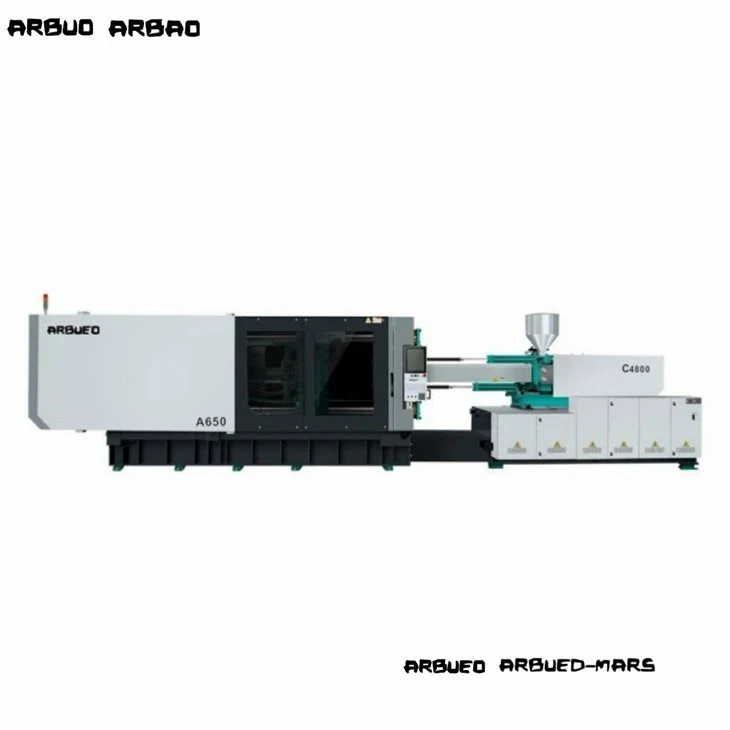
Servo Injection Molding Machines Manufacturer
Selecting hydraulic injection molding equipment for medium-to-high-volume manufacturing requires balancing energy costs, precision, cycle times, and machine longevity. Modern servo-hydraulic technology eliminates the thermal and electrical inefficiencies of traditional fixed-displacement pump systems while providing the clamp stability and high torque required for engineering resins.
This technical guide outlines performance specs, hydraulic configurations, sizing formulas, and mechanical options for engineering teams, procurement managers, and plant operations directors evaluating servo injection molding machinery for industrial scale-up or facility modernization.


Servo Injection Molding Machine Overview
A servo injection molding machine utilizes a dynamic closed-loop servo motor system to drive variable-displacement or fixed-gear internal pumps. Unlike conventional hydraulic machines where induction motors run continuously at nominal RPM regardless of process phase, a servo-driven system modulates motor speed and torque instantly based on real-time pressure and flow demands.
During non-action phases-such as cooling, mold pause, or robotic ejection-the servo motor drops to near-zero RPM. This operational shift yields three core benefits:
Energy Savings: Reduces hydraulic electrical consumption by 30% to 70% compared to standard fixed-displacement systems.
Thermal Management: Minimizes hydraulic fluid friction heating, reducing oil cooler water requirements and extending oil life.
Repeatability: Maintains response times under 50 ms for closed-loop injection pressure and position control, ensuring lower shot-to-shot weight variation.
Machine Configurations
INJECTION UNIT:
Servo Motor and Drive
Nitrided Screw and Barrel
Linear Guide Rail Carriage
CLAMPING UNIT:
Double-Toggle Kinematics
Cast Steel Platen (FEA Optimized)
Automatic Hydraulic Die-Height Adjust
SERVO-HYDRAULIC POWER PACK:
Permanent Magnet AC Servo Motor
Internal Gear Pump
High-Response Controller
Five-Point Double-Toggle System: Optimizes mechanical advantage, offering rapid platen travel at low pressure and high mechanical lockup force at final closure.
FEA-Optimized Ductile Iron Platens: Spheroidal graphite iron platens designed with low-deflection structural ribs to ensure uniform clamping pressure distribution across the mold face.
Automatic Lubrication System: Centralized volumetric grease distribution delivering measured lubricant to tie-bar bushings and toggle pins, reducing pin wear and particle contamination.
Hydraulic Die-Height Adjustment: Gear-driven platen height adjustment with digital encoder monitoring for rapid mold setup changes.
Twin-Cylinder Balanced Carriage: Dual hydraulic actuation cylinders apply balanced, axial forces to the screw carriage during injection to prevent nozzle misalignment and tilt.
Bimetallic / Nitrided Screw and Barrel: Standard SACM 645 nitrided steel barrel with options for tungsten-carbide bimetallic linings for glass-filled engineering resins.
Linear Guide Rail Movement: Low-friction linear motion guide rails on the injection carriage reduce mechanical stick-slip during micro-dosing and high-speed injection movement.
Product List
Model: A100 Compact
Clamping Force: 1,000 kN
Tie-Bar Clearance (H x V): 360 x 360 mm
Injection Capacity (PS): 145 g
Max System Pressure: 17.5 MPa
Target Application: Small precision electronics, connectors, sub-assemblies
Model: A170 Standard
Clamping Force: 1,700 kN
Tie-Bar Clearance (H x V): 460 x 460 mm
Injection Capacity (PS): 280 g
Max System Pressure: 17.5 MPa
Target Application: Technical components, medical housings, caps
Model: A230 Universal
Clamping Force: 2,300 kN
Tie-Bar Clearance (H x V): 530 x 530 mm
Injection Capacity (PS): 450 g
Max System Pressure: 17.5 MPa
Target Application: Home appliance parts, consumer goods, insert molding
Model: A290 Heavy-Duty
Clamping Force: 2,900 kN
Tie-Bar Clearance (H x V): 620 x 620 mm
Injection Capacity (PS): 720 g
Max System Pressure: 17.5 MPa
Target Application: Automotive interior trim, industrial pipe fittings
Model: A390 High-Volume
Clamping Force: 3,900 kN
Tie-Bar Clearance (H x V): 710 x 710 mm
Injection Capacity (PS): 1,250 g
Max System Pressure: 17.5 MPa
Target Application: Deep-draw containers, large housings, automotive covers
Model: A550 Industrial
Clamping Force: 5,500 kN
Tie-Bar Clearance (H x V): 830 x 830 mm
Injection Capacity (PS): 2,100 g
Max System Pressure: 17.5 MPa
Target Application: Large structural panels, crates, multi-cavity automotive components
Key Technical Features
Closed-Loop BUS Control Architecture:
Controller-to-servo communication utilizes EtherCAT or CANopen protocols, maintaining control loop response cycles under 1 ms.
High-Precision Linear Transducers:
Absolute optical/resistive position encoders with 0.01 mm resolution installed on clamping, injection, and ejector axes for position feedback.
PID Barrel Temperature Zones:
Multi-zone SSR (Solid State Relay) heating control with PID self-tuning algorithms maintains barrel zone tolerances within +/- 1 degree C.
Low-Pressure Mold Protection:
Variable pressure and speed settings monitor mold closure; sensitive torque-sensing algorithms trigger immediate mold reversal if resistance is encountered.
Core Pull and Unscrewing Interfaces:
Integrated programmable hydraulic core puller sequences (2-circuit standard) with options for hydraulic unscrewing motors.
Servo Hydraulic System and Energy Management
DYNAMIC CONTROL LOOP SEQUENCE:
System Controller -> Sends Digital Speed/Pressure Command to Servo Drive
Servo Drive -> Controls Permanent Magnet AC Servo Motor
AC Servo Motor -> Drives Internal Gear Pump
Internal Gear Pump -> Powers Hydraulic Actuators
Pressure Transducer -> Sends Real-Time Pressure/Flow Feedback to System Controller
System Architecture
The power unit pairs a Permanent Magnet Synchronous Motor (PMSM) with a low-noise internal gear pump. System pressure is monitored continuously via a digital transducer mounted directly on the pump outlet manifold.
Dynamic Control Loop
The machine controller calculates the required flow (Q) and pressure (P) for the specific machine phase (e.g., hold pressure, plasticizing, or platen travel).
Signals are sent to the servo drive via a digital fieldbus.
The servo drive adjusts the motor speed (n) to regulate flow and adjusts motor torque (tau) to regulate system pressure.
Pressure feedback loop frequency operates at 2 kHz, instantly reducing motor RPM during hold pressure or cooling down to standby levels, preventing energy waste over relief valves.
Servo vs. Conventional Hydraulic
Conventional: AC Induction Motor (Constant Speed)
Servo Hydraulic: Permanent Magnet Servo Motor (Variable Speed)
Impact: Eliminates power draw when machine is idle.
Conventional: Baseline (100%)
Servo Hydraulic: 30% to 70% Reduction
Impact: Lower operating expense per shot.
Conventional: High (Relief valve bypass generates heat)
Servo Hydraulic: Low (Delivers only requested oil volume)
Impact: Reduces chiller load and delays oil oxidation.
Conventional: Baseline (100%)
Servo Hydraulic: 50% to 70% Reduction
Impact: Lowers facility utility requirements.
Conventional: +/- 0.5% to +/- 0.8%
Servo Hydraulic: +/- 0.1% to +/- 0.3%
Impact: Reduces scrap rates on tight-tolerance engineering parts.
Conventional: 100 ms to 150 ms
Servo Hydraulic: Under 40 ms
Impact: Faster cycle initiation and pressure step control.
Conventional: 75 dBA to 85 dBA
Servo Hydraulic: Under 70 dBA
Impact: Improves shop-floor environmental safety compliance.
Technical Specifications
General Mechanical Parameters (Representative Platform A290)
Clamping Unit:
Clamping Force: 2,900 kN
Opening Stroke: 580 mm
Distance Between Tie Bars (H x V): 620 mm x 620 mm
Max. Mold Height: 650 mm
Min. Mold Height: 220 mm
Ejector Stroke: 160 mm
Ejector Force: 77 kN
Injection Unit (Screw Size B):
Screw Diameter: 55 mm
L/D Ratio: 20:1
Theoretical Injection Volume: 522 cm3
Shot Weight (PS): 475 g
Injection Rate: 210 cm3/sec
Max. Injection Pressure: 178 MPa
Screw Speed (Max): 0 to 190 RPM
Drive / Hydraulics / Electrical:
System Pressure: 17.5 MPa
Servo Motor Power: 37 kW
Heater Band Capacity: 16.5 kW
Oil Tank Capacity: 380 L
Machine Dimensions (L x W x H): 6.2 m x 1.6 m x 2.1 m
Dry Machine Weight: 9.2 Metric Tons
How to Select
Step 1: Clamping Force Calculation
Step 2: Shot Size and Volume Verification
Step 3: Dimensional Fit Check (Tie-Bar and Daylight)
Step 4: Injection Pressure Analysis
Step 5: Plasticizing Rate Evaluation
Step 6: Auxiliary and Core Hydraulic Circuits Configuration
Determine required clamp tonnage based on total projected area of the part plus runner system, multiplied by specific cavity pressure of the polymer:
Clamping Force (kN) = [Projected Area (cm2) x Cavity Pressure (bar) / 100] x Safety Factor (1.1 to 1.2)
Reference Cavity Pressures:
Polyolefin (PE/PP): 300 to 450 bar
Engineering Resins (PC, ABS, PA): 500 to 800 bar
Thin-wall packaging: 800 to 1100 bar
Match part mass to machine injection capacity. Select a screw size where the required shot volume (part + runner) consumes 30% to 80% of the barrel's maximum shot capacity:
Less than 20% Barrel Capacity: Risks resin degradation due to excessive residence time in the heated barrel.
Greater than 80% Barrel Capacity: Limits plasticizing consistency and reduces shot-to-shot thermal uniformity.
Verify mold width and height fit within the horizontal and vertical tie-bar clear distance (H x V).
Ensure minimum and maximum mold height dimensions accommodate the mold thickness.
Verify minimum opening stroke provides sufficient space to clear parts during robot end-of-arm tooling (EOAT) extraction.
Manufacturing and Quality Control
Platen Machining Precision: Platens are machined on 5-axis CNC horizontal gantry machining centers to ensure coplanar tolerances within 0.05 mm across the mounting faces.
Stress Relieving and Heat Treatment: Machine frames and platen castings undergo thermal stress-relief annealing to prevent structural deformation under continuous rated clamping loads.
Hydraulic System Testing: Hydraulic blocks undergo ultrasonic cleaning; systems are tested under 1.25x max working pressure to verify seal integrity and zero internal leakage bypass.
Dry Run Alignment: Every completed machine undergoes a mandatory 48-hour continuous dry-run test inspecting movement thermal signatures, tie-bar strain equilibrium, and noise limits before dispatch.
Quality Standard Compliance: Manufactured under ISO 9001 quality management systems; CE compliance verified for mechanical guard interlocks, electrical safety (EN 60204-1), and hydraulic safety standards.

Automotive Components
Target Parts: Door trims, HVAC louvers, engine covers
Requirements: High structural strength, low sink marks, dimensional consistency across ambient thermal ranges.
Resins: PP + 30% Glass Fiber, ABS/PC alloys, PA66.
Key Machine Feature: Multi-stage injection speed profile and core pull options for complex mold sliders.
Electrical and Electronics
Target Parts: Relay housings, terminal blocks, precision frames
Requirements: Tight tolerances, zero flash at parting lines, precise pin actuation.
Resins: PBT, LCP, Flame-Retardant ABS, Polycarbonate.
Key Machine Feature: High-response closed-loop injection pressure control to prevent over-packing micro-structures.
Industrial and Building Products
Target Parts: Pipe fittings, valves, cable glands
Requirements: Deep-draw injection capabilities, high melt delivery, thick-wall part packing without void formation.
Resins: Rigid PVC, HDPE, PPR.
Key Machine Feature: High-torque hydraulic plasticizing motors paired with optimized high-wear bimetallic screw profiles.
Specialized Screw and Barrel Assemblies:
UPVC screws with high-chrome plating and specialized tip designs.
Corrosive-resistant full-bimetallic barrels for fluoropolymer processing.
Mixing head geometries (Maddock / mixing pins) for masterbatch dispersion.
Hydraulic Modifications:
Accumulator-assisted high-speed injection systems for thin-wall applications.
Independent dual-pump hydraulic setups for simultaneous clamp movement and plasticizing (parallel recovery).
Hydraulic accumulators for fast injection speed response.
Automation and Interface Options:
EUROMAP 63 or SPI robot automation interfaces.
EUROMAP 73 / ANSI B11.20 safety interface protocols for robotic integration.
Hot-runner controller integration directly into machine HMI display screen.

Related Machines
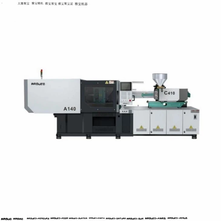
High-Speed Servo Injection Molding Machines: Optimized for thin-wall packaging, featuring accumulator support, upgraded injection speed (>300 mm/s), and fast toggle kinematics.
Two-Platen Servo Injection Molding Machines: Designed for large structural parts (800T to 3500T), offering a smaller footprint, extended opening stroke, and direct hydraulic clamping.
Multi-Material / Two-Color Machines: Equipped with dual injection units (L-shape, Parallel, or Piggyback setups) and integrated rotary tables for multi-shot molding.
Vertical Servo Injection Molding Machines: Vertical clamping and vertical injection designs optimized for manual or automated insert molding operations.
FAQ

Request a Quote
Need assistance selecting the correct clamp tonnage, screw size, or auxiliary interface for your molding line? Provide your production specs below to receive a detailed technical proposal, machine layout drawing, and quotation.
Target Part Dimensions (L x W x H mm):
Plastic Resin Type and Grade:
Part Weight (g) and Number of Cavities:
Estimated / Required Cycle Time (sec):
Facility Voltage Standard (e.g., 480V 3PH 60Hz / 400V 3PH 50Hz):
Technical support engineers are available to perform mold layout validation and clamp tonnage calculations prior to order placement.
We're professional servo injection molding machines manufacturers and suppliers in China, specialized in providing high quality customized service. We warmly welcome you to wholesale servo injection molding machines for sale here from our factory. For price consultation, contact us.