


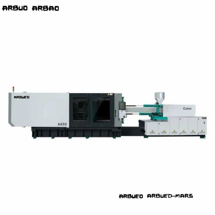
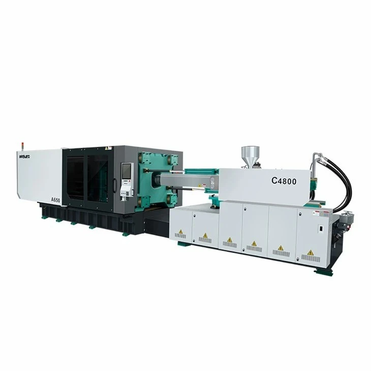
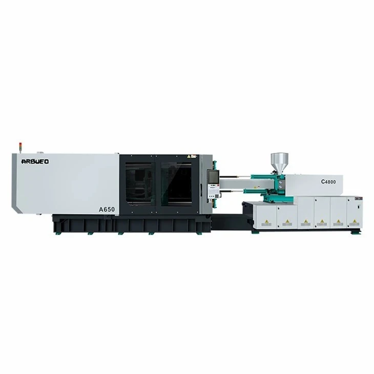
Servo Injection Molding Machine for High Cycle Production
High-cycle injection molding places distinct thermal and mechanical stresses on machine components. Standard hydraulic presses often experience fluid overheating, platen deflection, and hydraulic response lag when forced into dry cycle speeds below 2.0 seconds.
This servo-hydraulic platform utilizes high-response AC servo drives paired with internal gear pumps, optimized clamping kinematics, and accumulator-assisted injection. It maintains continuous cycle speeds down to 1.8 to 3.5 seconds without thermal hydraulic breakdown. Designed for multi-cavity molds, the machine reduces unit manufacturing costs in high-volume runs while cutting energy consumption by 30% to 60% compared to traditional fixed-displacement hydraulic systems.
Key Specifications
The values below reflect standard production configurations across the high-cycle product range.
|
Specification |
Unit |
Specification Range / Value |
|
Clamping Force |
kN / US Ton |
1,000 - 6,500 kN (112 - 730 US Tons) |
|
Tie-Bar Clearance (H x V) |
mm |
410 x 410 to 920 x 920 |
|
Platen Dimensions (H x V) |
mm |
610 x 610 to 1,380 x 1,380 |
|
Ejection Stroke / Force |
mm / kN |
100 - 220 mm / 35 - 160 kN |
|
Screw Diameter Options |
mm |
28 to 90 (A/B/C Screw Ratios available) |
|
Injection L/D Ratio |
L/D |
20:1 - 24:1 (Application-dependent) |
|
Max. Injection Speed |
mm/s |
300 - 800 (Accumulator-assisted) |
|
Injection Pressure |
bar |
1,600 - 2,400 |
|
Dry Cycle Time (Euromap 6) |
sec |
1.4 - 2.8 |
|
System Pressure |
bar |
17.5 MPa (175 bar) |
|
Pump Drive System |
Type |
Phase/Inovance Servo Motor + Sumitomo/Eckerle Gear Pump |
|
Control System |
Controller |
Austria KEBA Touchscreen / Techmation |
Key Features
Accumulator-Assisted Injection Unit: Nitrogen accumulators deliver high peak flow rates during the filling stage, enabling injection speeds up to 800 mm/s for thin-wall sections without overloading the main hydraulic pumps.
Five-Point Double-Toggle Clamping Kinematics: Computer-optimized toggle geometry delivers fast platen movement during opening and closing, changing to high force delivery as the mold touches.
Dual-Cylinder Balanced Injection Structure: Twin parallel injection cylinders maintain axial alignment during high-pressure injection, preventing screw deflection and uneven barrel wear.
Closed-Loop Servo System: High-resolution rotary encoders on servo motors work in conjunction with linear transducers on clamping, injection, and ejection axes to maintain position repeatability within +/- 0.1 mm.
Independent Hydraulic Circuit Control: Separate valve blocks for clamping, plasticizing, and core-pull functions allow simultaneous machine movements, reducing total cycle time.
Machine Configuration
System Architecture
AC Servo Drive System drives the Internal Gear Pump.
Pressure flows through the Proportional Valve Block to three main subsystems:
Clamping Unit: 5-Point Toggle, Finite Element Analysis (FEA) Box Platen, Linear Guide Rails.
Injection Unit: Dual Parallel Cylinders, Bi-Metallic Screw and Barrel, Servo Electric Plasticizing Motor (Optional).
Accumulator Station: High-Speed Fill Boost up to 800 mm/s.
Detailed Subsystems
Clamping Structure: Platens are cast using ductile iron (QT500-7) and analyzed via Finite Element Analysis (FEA) to minimize deflection under full tonnage. Toggle pins run on self-lubricating graphite-impregnated bronze bushings, eliminating continuous grease contamination on mold surfaces.
Injection and Plasticizing Unit: The screw profile uses a high-mixing, barrier-type design to maintain melt homogeneity at high plasticizing speeds. Nitrided or bi-metallic barrels (PTA alloy lined) handle abrasive additives such as glass fiber or calcium carbonate.
Hydraulic and Drive Unit: An AC synchronous servo motor drives an internal gear pump. Motor speed dynamically scales down to near-zero during cooling and dwell phases, reducing oil temperatures and cutting cooling water demand by up to 40%.
Product-Specific Technical Advantages
Thermal Stability Under Continuous Fast Cycles
In high-cycle applications, oil degradation from fluid shear is a primary cause of valve failure and positional drift. This system utilizes oversized oil coolers combined with targeted oil flow pathways inside the main manifold. Hydraulic oil temperatures remain stable between 40°C and 48°C even during 24/7 continuous runs in ambient plant temperatures up to 45°C.
Low-Deflection Platen Rigidity
Standard platens flex under high clamping forces, causing flash on thin-wall container edges and wearing mold core pins prematurely. The box-frame design concentrates clamping force directly through the mold center, keeping platen parallelism within 0.08 mm across full stroke, which extends mold maintenance intervals.
Energy Consumption Profiles
Below is a measured power consumption comparison during a 4.2-second cycle producing 4-cavity food containers:
|
Power Stage |
Fixed-Displacement Pump Press |
High-Cycle Servo Press |
Energy Reduction |
|
Clamping / Unclamping |
18.5 kW |
6.2 kW |
66.4% |
|
Injection / Holding |
24.0 kW |
14.8 kW |
38.3% |
|
Plasticizing |
15.0 kW |
11.2 kW |
25.3% |
|
Cooling / Idle |
12.0 kW |
0.4 kW |
96.6% |
|
Average Total Demand |
17.37 kW/h |
8.15 kW/h |
53.0% |
Typical Applications
Packaging and Thin-Wall Containers: Disposable food tubs, beverage closures, pails, and hinged caps requiring fill wall thicknesses down to 0.4 mm and high multi-cavity output.
Medical Consumables: Syringe barrels, petri dishes, blood collection tubes, and pipette tips molded under ISO Class 7 or 8 cleanroom constraints requiring low-outgassing hydraulic fluids and oil-free tie-bar options.
Electrical and Technical Parts: Precision connector housings, terminal blocks, and electronic enclosures where tight dimensional tolerances (+/- 0.02 mm) must be maintained across large batch quantities.
Material Compatibility
The injection unit supports a broad range of thermoplastic polymers when equipped with application-matched screw profiles:
|
Resin Family |
Grade Compatibility |
Specific Screw Configuration Required |
|
PP / PE |
High MFI (20 - 100 g/10 min) |
Standard high-mixing profile; rapid-check ring valve. |
|
PS / ABS |
General Purpose / High Impact |
High-speed barrier screw to prevent thermal degradation. |
|
PET |
Packaging & Preforms |
Extended L/D ratio (24:1), high-torque drive, specialized flight profile. |
|
PC / PMMA |
Optical & Precision Grades |
Hardened bi-metallic barrel, wider flight pitch, low-compression screw. |
|
PA66 / PBT (+GF) |
Filled Engineering Resins |
Fully hardened PTA-welded bi-metallic screw and barrel assembly. |
Configuration Options & Selection Guide
Step-by-Step Selection Workflow
Step 1: Calculate Clamping Force
Tonnage = Projected Area (cm²) x Cavities x Injection Factor
(Factor: 0.3 - 0.5 kN/cm² for PE/PP; 0.6 - 0.8 kN/cm² for PC)
Step 2: Match Injection Unit & Plasticizing Rate
Shot Volume = 30% to 70% of Max Barrel Capacity
Injection Speed > Fill Time Requirements (<0.5s)
Step 3: Select Optional High-Cycle Modules
Servo electric lap plasticizing
Hydraulic accumulator fill-assist
Air blow valves / Core pulls
Recommended Configuration Modules
Standard Thin-Wall Module: Nitrogen accumulator + extended L/D bi-metallic screw + air ejection valves + KEBA i3000 controller.
Cleanroom Medical Module: Nickel-plated platens + non-grain hydraulic oil + closed-loop air ejection + servo-electric plasticizing motor (eliminates hydraulic oil near the mold area).
Engineering Plastic Module: High-wear PTA bi-metallic barrel + ceramic heater bands + high-pressure injection unit up to 2,400 bar.
Manufacturing & Quality Control
Machines are built under ISO 9001 quality management processes across structured production steps:
Frame Welding & Stress Relieving: Machine bases are fabricated from heavy-gauge structural steel and undergo thermal annealing to relieve internal stresses before machining, preventing frame warping over long-term operation.
Precision Machining: Platens and clamping frames are machined on multi-axis CNC gantry centers in a single setup to maintain critical hole tolerances and mounting surface flatness.
Hydraulic System Flushing: All manifold blocks and hydraulic lines undergo high-velocity flushing to ISO 4406 cleanliness standards (Class 16/14/11) prior to valve installation, reducing early component wear.
Load & Run-In Testing: Every machine undergoes a minimum 72-hour continuous run-in test under full hydraulic pressure, including thermal imaging scans of electrical panels and high-pressure leak checks.
Customization & OEM Support
Machines can be tailored to specific factory automation setups and tooling requirements:
Custom Screw & Barrel Metallurgy: Specific alloys and coatings for processing corrosive (PVC/PVDF) or highly abrasive (up to 50% glass-fiber) materials.
Automation Integration Options: Euromap 67 or Euromap 73 interfaces for side-entry robots, top-entry sprue pickers, and downstream packaging lines.
Hydraulic Core Pull Expansion: Configurable valve banks for up to 4-stage core pull and unscrewing sequences controlled directly via the main touchscreen interface.
Custom Voltage Options: Electrical cabinets configured to 220V, 380V, 415V, 460V, or 480V (3-Phase, 50/60 Hz) per regional plant specifications.
Technical Information Required for Quotation
To receive an accurate technical quotation and machine sizing report, please provide the following project details:
Part Information: Part drawing/3D step file, material grade (MFI/MFR if available), wall thickness dimensions, and target part weight.
Mold Specifications: Mold dimensions (Width x Height x Thickness), weight, number of cavities, and hot runner system details.
Production Output Target: Required cycle time, daily output volume, or required automation/robotics integration.
Plant Electrical & Utility Context: Available primary power supply voltage/frequency and cooling water supply parameters.
FAQ
Q: What dry cycle times does this high-cycle machine achieve?
A: Depending on clamp tonnage and stroke length, dry cycle times range between 1.4 seconds for 1,000 kN models and 2.8 seconds for 6,500 kN models (calculated per Euromap 6 standards).
Q: How does a servo hydraulic system compare to an all-electric press for high-cycle applications?
A: All-electric presses offer high precision and lower noise, but carry significantly higher capital investment costs and elevated repair costs for ball screws under extreme continuous loads. High-cycle servo hydraulic machines provide 90% to 95% of the energy efficiency and accuracy of all-electric presses at a lower initial equipment cost and with lower long-term mechanical maintenance costs.
Q: Can this machine process biodegradable resins like PLA?
A: Yes. Processing PLA or PHA requires a low-shear screw profile and precise barrel temperature zoning to prevent polymer degradation. Specify PLA requirements during technical inquiry to ensure the appropriate screw profile is fitted.
Q: What interface standards are provided for robot connection?
A: Machines come standard with Euromap 67 robot interfaces. Euromap 73 or custom SPI interfaces can be fitted upon request.
Q: What is the standard warranty and spare parts availability?
A: Standard supply includes a 12-month complete machine warranty and a 24-month structural warranty on platens and tie-bars. Replacement hydraulic components, valves, and electrical components utilize internationally available brands (e.g., Rexroth, Yuken, Schneider, KEBA) for local sourcing capability.
Hot Tags: servo injection molding machine for high cycle production, China servo injection molding machine for high cycle production manufacturers, suppliers, factory


