


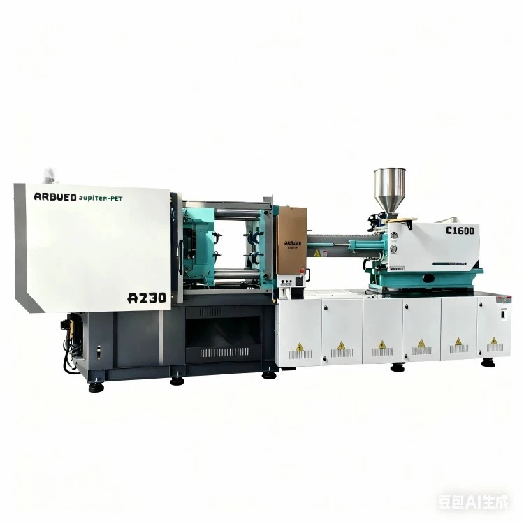
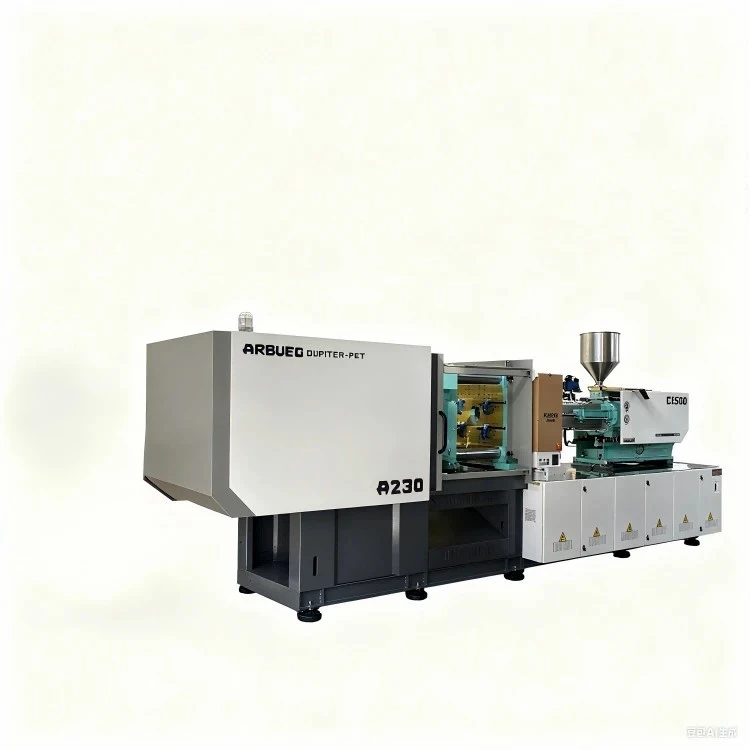
Servo-Hydraulic Injection Molding Machine
The servo-hydraulic injection molding machine combines the raw clamping power and hydraulic durability of traditional systems with the precise, energy-efficient dynamic response of permanent-magnet AC servo drives. Built on a rigid five-point internal toggle clamping framework, this machine reduces energy consumption by 40% to 70% compared to fixed-displacement pump systems while maintaining positional repeatability within +/- 0.05 mm.
Designed for mid-to-high volume plastic manufacturing across automotive, packaging, electrical, and consumer goods industries, the system handles resin processing from commodity thermoplastics (PP, PE, PS) to filled engineering polymers (PA66+30%GF, PC/ABS, PBT).
By continuously matching motor speed directly to system pressure and flow requirements, oil temperature remains stable throughout operation. This minimizes thermal degradation of hydraulic fluid, extends seal lifespan, and delivers shot-weight consistency across extended production runs.
Key Specifications
The table below outlines technical parameters for standard machine configurations across representative tonnage classes.
|
Specification |
Unit |
90-Ton |
160-Ton |
260-Ton |
480-Ton |
|
Clamping Force |
kN (tonf) |
900 (90) |
1600 (160) |
2600 (260) |
4800 (480) |
|
Toggle System |
- |
5-Point Twin Toggle |
5-Point Twin Toggle |
5-Point Twin Toggle |
5-Point Twin Toggle |
|
Tie-Bar Clearance (H x V) |
mm |
360 x 360 |
460 x 460 |
580 x 580 |
810 x 800 |
|
Mold Platen Dimensions (H x V) |
mm |
530 x 530 |
680 x 680 |
860 x 860 |
1180 x 1170 |
|
Max / Min Mold Height |
mm |
380 / 150 |
500 / 180 |
620 / 220 |
800 / 320 |
|
Clamping Stroke |
mm |
320 |
430 |
540 |
780 |
|
Ejector Stroke / Force |
mm / kN |
100 / 33 |
130 / 45 |
160 / 67 |
220 / 120 |
|
Screw Diameter Options (A / B / C) |
mm |
30 / 35 / 40 |
40 / 45 / 50 |
50 / 55 / 60 |
70 / 75 / 80 |
|
L/D Ratio (B Screw) |
L/D |
21.5:1 |
22:1 |
22.4:1 |
23.1:1 |
|
Theoretical Shot Volume (B Screw) |
cm³ |
153 |
286 |
570 |
1546 |
|
Shot Weight (PS - B Screw) |
g |
139 |
260 |
519 |
1407 |
|
Injection Pressure (B Screw) |
bar |
1850 |
1780 |
1862 |
1720 |
|
Injection Rate (B Screw) |
cm³/s |
105 |
145 |
228 |
420 |
|
Screw Speed (Max) |
rpm |
220 |
200 |
185 |
150 |
|
System Pressure |
bar |
160 |
160 |
160 |
160 |
|
Servo Pump Motor Power |
kW |
11 |
15 |
22 |
45 |
|
Heating Power |
kW |
6.5 |
9.8 |
16.5 |
29.5 |
|
Hydraulic Oil Tank Capacity |
L |
160 |
230 |
380 |
720 |
|
Dry Weight |
Metric Ton |
3.2 |
5.2 |
8.8 |
19.5 |
Key Features
Dynamic Servo Drive System: Permanent magnet AC servo motor combined with an internal gear pump delivers response times under 50 ms from zero to maximum output. Motor stops during cooling phases, reducing ambient noise (< 72 dB) and overall electrical loads.
Rigid Platen Structure: Box-type platen designs optimized via Finite Element Analysis (FEA) reduce center deflection under maximum clamp tonnage. This ensures uniform clamping pressure distribution across mold surfaces, preventing flash and extending tool life.
Closed-Loop PID Control: Real-time sensor feedback monitors system pressure, screw displacement, and barrel thermal zones, maintaining process repeatability within tight operational windows.
Heavy-Duty Tie-Bars: Hard-chrome plated, high-tensile steel tie-bars with rolled threads resist strain fatigue and maintain parallel alignment over extended production cycles.
Industrial Controller: Dedicated multi-CPU microprocessor interface with a 12-inch color touchscreen display, hosting multi-language support, real-time graphical process tracking, SPC data collection, and USB/Ethernet output ports.
Technical Advantages
Energy Efficiency & Thermal Stability
Traditional hydraulic molding machines utilize fixed-displacement induction motors running continuously at maximum speed, bypassing unused pressurized oil back to the reservoir through relief valves. This practice converts excess mechanical energy into waste heat, requiring large chillers to cool hydraulic fluid.
Traditional System: [Induction Motor (Fixed RPM)] --> [Fixed Pump] --> [Bypass Valve (Heat Loss)] --> [Hydraulic Tank]
Servo System: [Servo Driver + Control Signal] --> [PM Servo Motor (Variable RPM)] --> [Internal Gear Pump]
Our servo-hydraulic drive dynamically modulates motor rotation (0 to 2,500 rpm) to match real-time flow and pressure demands.
Cooling Phase Savings: The pump motor drops to zero speed while the part cools inside the mold, drawing minimal idling current.
Reduced Oil Cooling Demands: Lower thermal energy transfer into the hydraulic fluid keeps oil temperature between 40°C and 50°C under continuous load, eliminating high cooling water consumption and slowing fluid oxidation.
Mechanical Precision & Structural Rigidity
High-Linearity Transducers: Non-contact magnetostrictive linear position sensors monitor mold closing, clamping force, injection stroke, and ejector positions at sub-millimeter resolutions.
Platen Deflection Suppression: Moving platens are supported on low-friction hardened steel guide shoes along the machine frame rather than hanging exclusively on tie-bars, preventing uneven mold wear and center sag.
Balanced Injection Cylinder Layout: Dual-pull hydraulic injection cylinders balance axial thrust forces evenly across the screw centerline, preventing tilting and barrel wear.
Typical Applications
Automotive: Interior trim clips, door handle housings, HVAC ducting assemblies, fuse boxes, and dashboard structural brackets.
Packaging: Thick-wall caps, thread closures, storage container lids, crates, and structural shipping buckets.
Consumer Goods & Electronics: Power tool enclosures, appliance covers, TV frames, battery cases, and junction boxes.
Building Products: PVC/PPR pipe fittings, wall plate covers, conduit connectors, and drainage component housings.
Industrial Parts: Cable ties, caster wheels, conveyor components, and pump impellers.
Material Compatibility
Processing performance depends on screw geometry and heating zone configurations designed for specific polymer characteristics:
Standard Nitrided Screws: Suitable for non-abrasive polyolefins (PP, PE, PS, ABS, HIPS, SAN).
Bimetallic Barrel & Screw Sets: Required when processing glass-fiber reinforced polymers (PA6/66 + 30% GF, PBT + 20% GF) to withstand abrasive mechanical wear.
Corrosion-Resistant Packages: Chrome-plated or nickel-alloy screws designed for heat-sensitive halogenated polymers (PVC, PVDF) that generate corrosive acid vapors during melt processing.
Configuration Options & Selection Guide
To determine the correct machine configuration, review key part parameters against baseline specifications:
Calculating Required Clamping Force:
Clamping Force (Tons) = [Total Projected Area of Parts and Runners (cm²) x Cavity Pressure (bar)] / 1000
General Guideline: Thin-wall packaging requires 0.6 - 0.8 tons/cm²; general industrial parts require 0.3 - 0.5 tons/cm².
Shot Capacity Sizing:
Ensure total shot weight (part plus runner system) falls between 20% and 80% of the machine's maximum rated theoretical shot capacity.
Sizing Rule: Under 20% risks thermal degradation due to long resin residence times; over 80% compromises melt homogeneity and process stability.
Screw Option Selection:
A-Screw: High pressure, smaller volume. Ideal for thin-wall engineering parts (PC, PA).
B-Screw: Balanced standard design. Recommended for general purpose molding (PP, ABS, PS).
C-Screw: High shot volume, reduced pressure. Optimized for soft commodity resins and thick-walled parts.
Manufacturing & Quality Control
Every machine undergoes standardized manufacturing and quality validation protocols prior to shipment:
[Raw Material Inspection] --> [CNC Machining & Platen FEA] --> [Assembly & Hydraulic Line Flushing]
|
[Shipment] <-- [48-Hour Dry Run & Full Load Testing] <-- [Electrical & Pressure Testing]
Machining Precision: Platen mounting faces, tie-bar bores, and machine bases are machined in a single setup on large horizontal CNC machining centers to ensure squareness and parallelism.
Hydraulic System Flushing: Hydraulic manifolds undergo multi-stage ultrasonic cleaning. Oil lines are flushed through sub-micron filter rigs to meet ISO 4406 cleanliness standards (Target: 16/14/11) prior to factory runoff.
Testing Protocol:
Static Pressure Testing: Hydraulic systems are held at 125% maximum operational pressure (200 bar) for 4 hours to check for leaks and valve integrity.
Dynamic Load Runoff: Every machine runs a 48-hour continuous dry-cycle test under full clamping force to verify sensor calibration, thermal stability, and toggle smooth-motion profiles.
Customization & Auxiliary Integration
Core Pulling Systems: Expandable double or quadruple hydraulic core-pull circuits driven by proportional valves for complex molds with moving side-actions.
Integrated Hot Runner Controllers: Built-in multi-zone temperature control modules managed directly through the main controller interface.
Automation Interface: Standard Euromap 67 / SPI 50-pin robot interfaces for side-entry and top-entry part retrieval systems.
Specialized Injection Units:
Unscrewing hydraulic motor attachments for threaded caps and pipe fittings.
Accumulator-assisted high-speed injection systems for thin-wall packaging applications.
Technical Information Required for Quotations
To receive an accurate technical proposal and machine specification match, submit the following details:
Part Specifications: Part dimensions, 3D CAD files (.STEP/.IGS), projected surface area, and wall thickness range.
Resin Details: Specific polymer grade, manufacturer data sheet, density (g/cm³), and shrinkage rate percentage.
Mold Layout: Number of cavities, total runner mass, mold dimensions (length x width x height), mold weight, and core pull requirements.
Production Requirements: Desired cycle time, annual target volume, and power utility standards (e.g., 480V 60Hz 3-Phase / 380V 50Hz 3-Phase).
FAQ
Q: How does a servo-hydraulic system compare to an all-electric injection molding machine?
A: All-electric machines offer higher axial repeatability (+/- 0.01 mm vs. +/- 0.05 mm) and lower energy use in small tonnage applications. However, servo-hydraulic systems provide greater clamping force capability above 400 tons, higher load durability, and a 30% to 50% lower initial capital expenditure while capturing most of the energy savings of all-electric designs.
Q: What power supply requirements are needed for overseas installation?
A: Machines are configured to local industrial power grids during manufacturing. Standard configurations include 380V/50Hz/3-Phase for European and Asian markets, and 460V-480V/60Hz/3-Phase for North American facilities. Step-down or isolation transformers can be integrated into the main cabinet upon request.
Q: What maintenance schedule is required for hydraulic oil and filtration?
A: Initial hydraulic oil changes are recommended after the first 500 operational hours. Under standard operating conditions with stable oil temperatures below 50°C, subsequent oil replacement intervals are every 4,000 to 5,000 operational hours. Return oil filters should be replaced every 2,000 hours.
Q: What spare parts are included for international shipments?
A: Standard consignment wear kits include barrel heating bands, thermocouples, hydraulic cylinder seal kits, high-pressure hose assemblies, and a spare linear position transducer.
Hot Tags: servo hydraulic injection molding machine, China servo hydraulic injection molding machine manufacturers, suppliers, factory


