


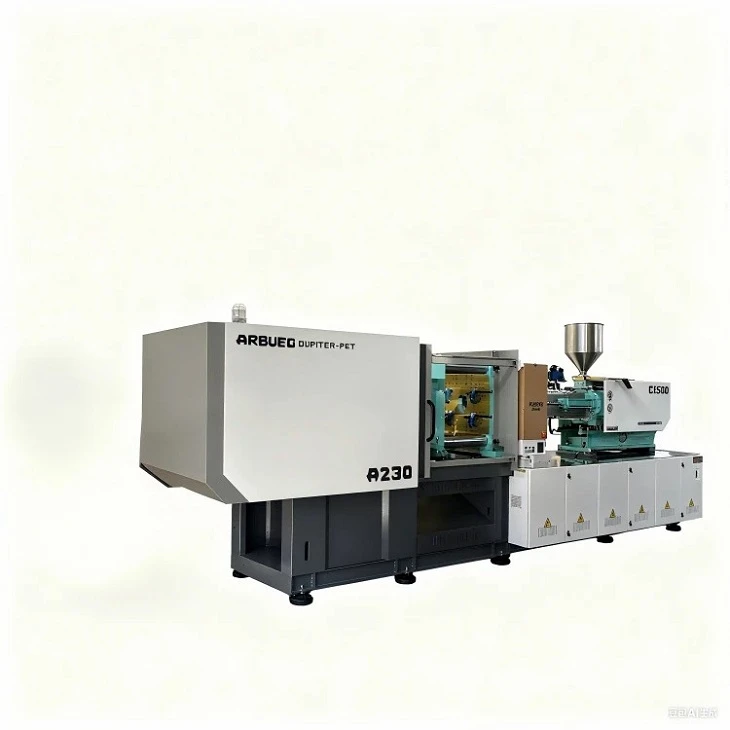
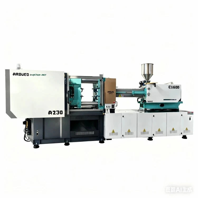
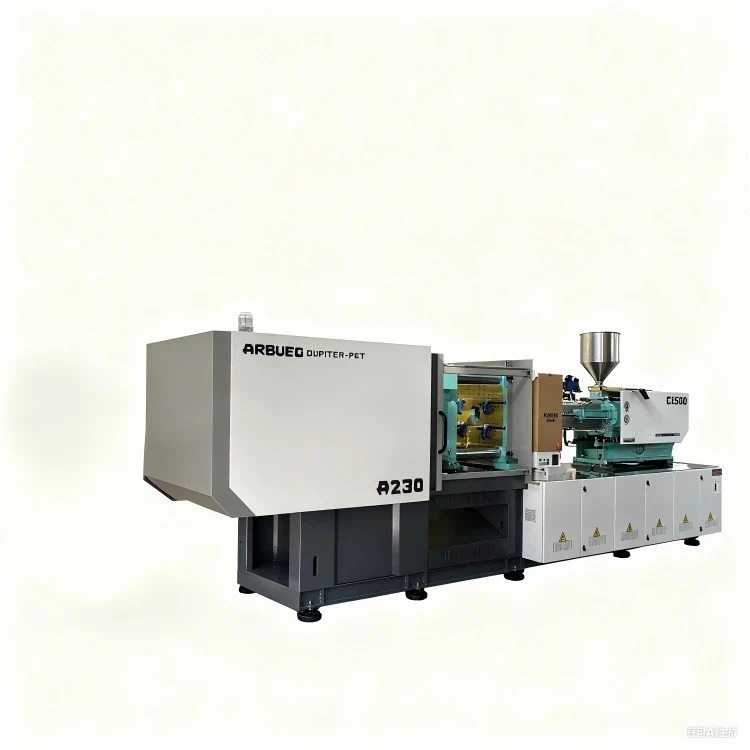
High-Speed Packaging Injection Molding Machine
This high-speed injection molding machine is built specifically for thin-wall packaging applications requiring fast cycle times, precise injection control, and continuous 24/7 operation. Engineered with a high-rigidity clamping unit and an optimized accumulator-assisted injection system, it reliably produces food containers, thin-wall buckets, closures, and medical packaging with wall thicknesses down to 0.4 mm.
By integrating a low-inertia injection response with parallel hydraulic motions, this system cuts overall cycle times to 2.5–5 seconds depending on part geometry and mold design. The overall engineering focus emphasizes shot-to-shot consistency, structural durability under high dynamic loads, and energy efficiency via servo-hydraulic drive technology.
Key Specifications
|
Specification Parameter |
Value / Range |
Unit / Note |
|
Clamping Force |
2,000 – 5,500 |
kN (200 – 550 Ton) |
|
Injection Speed |
300 – 800 |
mm/s (Accumulator-driven) |
|
Injection Response Time |
<= 25 |
ms |
|
Tie-Bar Clearance (H x V) |
560 x 560 to 880 x 880 |
mm |
|
Screw Diameter Options |
32 / 38 / 42 / 48 / 55 |
mm (L/D Ratio: 22:1 – 24:1) |
|
Max. Shot Weight (PS) |
120 – 680 |
g |
|
System Pressure |
17.5 – 21 |
MPa |
|
Dry Cycle Time |
1.2 – 1.8 |
s (Euromap 6) |
|
Ejector Force / Stroke |
60 – 120 kN / 150 – 220 mm |
Hydraulic parallel ejector standard |
|
Drive System |
Servo-pump + Hydraulic Accumulator |
Hybrid response system |
Key Features
Accumulator-Assisted High-Speed Injection: Nitrogen accumulators deliver instantaneous hydraulic flow, driving injection speeds up to 800 mm/s to fill ultra-thin cavities before melt freezing occurs.
Synchronized Parallel Movements: Independent hydraulic circuits permit simultaneous platen opening, plasticizing, and ejection during part discharge, reducing total cycle overhead.
High-Rigidity Platen Structure: Finite Element Analysis (FEA)-optimized box platens ensure uniform clamping force distribution, minimizing platen deflection and extending mold core/cavity lifespan.
Low-Inertia Injection Unit: Dual-injection cylinder configuration provides balanced axial thrust, reducing mechanical vibration during high-acceleration plasticizing and injection phases.
Closed-Loop Servo System: High-response electro-hydraulic proportional valves paired with linear optical encoders provide position feedback accurate to within +/- 0.1 mm.
Working Principle & Machine Configuration
High-speed thin-wall molding requires rapid melt delivery before the polymer cools below its flow temperature.
Plasticizing Phase: The servo drive powers a dedicated nitrided screw, converting resin pellets into a homogenous melt. Backpressure is digitally controlled via closed-loop feedback.
Accumulator Charge & Injection: Hydraulic accumulators store pressure during cooling. Upon mold lockup, high-speed proportional valves release stored energy, accelerating the injection cylinder to set speed in under 25 milliseconds.
Clamping & Tie-Bar Balancing: A heavy-duty five-point double-toggle mechanism locks the platen. Strain gauges monitor tie-bar tension to maintain equal force across all four bars, eliminating asymmetric flash.
Synchronized Ejection: Air-blow circuits work alongside hydraulic ejectors to release parts immediately as platens reach daylight clearance.
Product-Specific Technical Advantages
Reduced Mold Wear via Balanced Clamping: Tie-bar stress variance remains under 3% across full clamping cycles, preventing uneven parting-line wear on multi-cavity hot runner molds.
Stable Plasticizing Under Fast Cycles: High-torque hydraulic motors maintain consistent melt homogeneity without thermal degradation, even at screw speeds exceeding 300 RPM.
Lower Energy Consumption per Part: Variable-displacement servo pumps reduce standby power consumption by 30% to 55% compared to fixed-displacement pump systems.
Precision Pressure Transition: Linear position sensors provide rapid switching from velocity control to holding pressure control, preventing sink marks or over-packing on delicate rim sections.
Typical Applications
Food & Beverage Packaging
Thin-Wall Containers: IML (In-Mold Labeling) food tubs, ice cream tubs, and deli boxes (wall thickness 0.45 mm – 0.75 mm).
Closures & Caps: High-cavitation beverage caps, flip-tops, and oil bottle spouts requiring tight thread tolerances.
Industrial Packaging
Pails & Buckets: 1L to 20L paint pails, chemical drums, and heavy-duty storage crates requiring reinforced rims and structural ribs.
Medical & Disposable Products
Laboratory Consumables: Pipette tips, Petri dishes, and test tube racks produced under cleanroom conditions.
Medical Packaging: Syringe barrels, needle shields, and diagnostic cartridge housings.
Material Compatibility
|
Resin Type |
MFI / MFR Range |
Typical Application |
Key Machine Requirement |
|
PP (Polypropylene) |
25 - 100 g/10 min |
Food containers, packaging tubs |
High-speed injection, optimized heating zones |
|
HDPE |
4 - 25 g/10 min |
Caps, closures, industrial pails |
High injection pressure, durable screw tip |
|
PS / GPPS |
8 - 20 g/10 min |
Cutlery, clear deli lids, Petri dishes |
Precise hold pressure to avoid brittleness |
|
PET |
Intrinsic Viscosity 0.72 - 0.85 |
Preforms, specialized containers |
High-torque drive, low-shear screw geometry |
How to Select / Configuration Options
Clamping Force Calculation
Calculate required clamping force based on projected part area and cavity pressure:
Clamping Force (kN) = Projected Area (cm2) x Cavity Pressure (bar) x 1.15 (Safety Factor)
For Thin-Wall Containers: Use average cavity pressures between 600 bar and 800 bar.
For Standard Packaging: Use average cavity pressures between 350 bar and 500 bar.
Machine Configuration Matrix
|
Production Goal |
Injection Unit Choice |
Screw Type |
Recommended Options |
|
Ultra-Thin Wall (< 0.5 mm) |
Accumulator Boosted (> 600 mm/s) |
Bimetallic High-Mix Screw |
Pneumatic core pulls, air-blow valves, IML interface |
|
High-Cavitation Caps (32+ Cav.) |
Standard Servo High-Speed (400 mm/s) |
Wear-Resistant Nitrided Screw |
Continuous thread-unscrewing motor, dynamic backpressure |
|
Deep-Draw Pails (10L - 20L) |
High-Torque Injection Unit |
Heavy-Duty Barrier Screw |
Hydraulic core pulling, robot pick-and-place interface |
Manufacturing & Quality Control
Structural Machining: Machine frames, platens, and toggles undergo stress-relief annealing prior to CNC machining to prevent long-term frame deformation.
Precision Component Verification: Tie-bars and screws are ground to target tolerances (+/- 0.008 mm) and inspected via CMM (Coordinate Measuring Machine) systems.
Hydraulic System Testing: Hydraulic blocks undergo pressure-burst testing at 1.5 times operating pressure and fluid cleanliness checks to ISO 4406 standards.
Run-in Testing: Every unit completes a 72-hour continuous dry-run cycle and a full-load injection test prior to shipment, verifying clamp speed, temperature stability, and sensor response times.
Customization & OEM Support
Machines can be tailored to meet integrated cell requirements and facility automation standards:
Custom Screw Geometries: Specialized L/D ratios and flight profiles optimized for color masterbatch mixing or recycled content processing (rPET, rPP).
Automation & Robotics Interfacing: Euromap 67 and Euromap 73 standardized interfaces allow plug-and-play connection with side-entry IML robots, top-entry takeaway arms, and conveyor systems.
Custom Voltage & Safety Compliance: Electrical panels wired to standard global line voltages (380V/50Hz, 460V/60Hz, 230V/60Hz) with CE or UL safety enclosure compliance.
What Buyers Should Provide for a Quote
To receive an itemized technical proposal and machine sizing recommendation, submit the following engineering parameters:
Part Drawings / Samples: 3D CAD files (.STEP or .IGS format) including wall thickness distribution, part weights, and runner system design.
Mold Specifications: Number of cavities, mold dimensions (Length x Width x Height), shut-height requirements, and hot runner power load.
Target Output: Desired hourly production rate, target cycle time, and material specification (including melt flow index and resin supplier).
Downstream Requirements: Automation needs (In-Mold Labeling, robotic extraction, vision inspection) and utility availability (chilled water capacity, air compressor specifications).
FAQ
Q: What injection speed is required for thin-wall packaging applications?
A: Thin-wall packaging (wall thickness below 0.6 mm) generally requires injection speeds between 400 mm/s and 800 mm/s. Fast filling prevents resin solidification prior to complete cavity packing.
Q: How does hydraulic accumulator integration impact machine performance?
A: Accumulators store hydraulic energy during non-injection phases of the cycle and discharge it instantly during filling. This permits ultra-high injection speeds without requiring disproportionately large hydraulic pump motors.
Q: Can this machine handle post-consumer recycled (PCR) materials?
A: Yes. For materials containing PCR or regrind up to 50%, we recommend specifying bimetallic barrel and screw packages along with melt-filtering nozzles to protect against particulate contamination.
Q: What is the average lead time for production and delivery?
A: Standard machine configurations undergo factory assembly and run-in testing within 35 to 45 days. Customized configurations or specific automation integrations typically require 60 days prior to factory acceptance testing (FAT).
Hot Tags: high speed packaging injection molding machine, China high speed packaging injection molding machine manufacturers, suppliers, factory


